|


|
Construction Details
Here are some drawings, pictures and construction notes pertainning to the Launcher.
|
This page shows pictures and drawings of the launcher, in the
event someone wants to build one. As noted on page one (Project
Overview), I will likely simplify and improve on it during the next
few years.
|
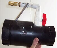 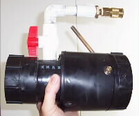
Above are pictures of the rear half of left & right side of the com-
bustion chamber. The metering tube (with valve & quick disconnect)
and pressure gauge can be seen in both views. On the left side
you can see the electrical connections for the mixing fan. On the
right hand side you can see the twist knob for the lantern lighter.
|
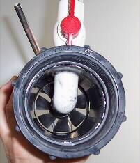 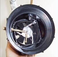
Above are pictures of the rear view & front view of the inside
of the rear portion of the combustion chamber. The mixing fan (80
mm from a computer power supply) is visible from both views. In
the left photo you can see the distribution manifold pipe. In the right
photo you see the lantern lighter on the left side, the end of the tire
pressure gauge on the upper right side. In the right photo you
can also see foil that I glued on the fan to protect it from the ignition
flame.
|
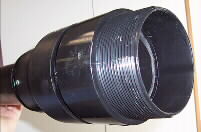 
Above are pictures of the front half of the combustion chamber
and barrel. In the photo on the right you can see four screws which
serves to both help mechanically hold the barrel to the transisiton
member and to keep the tennis ball from being plunged back into
the combustion chamber.
|
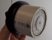
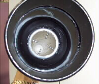
Here we see the rear vent
cover that threads into the back.
Note that to reduce the com-
bustion area & keep it forward
I installed a block on it. The
spraypaint can lid on the front
had to be replaced with a block
of wood after one firing broke the
rather thin plactic.
|
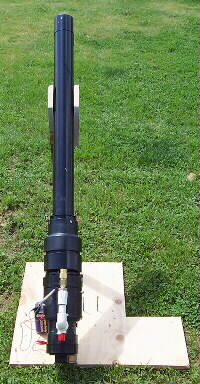 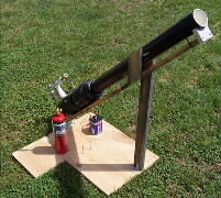
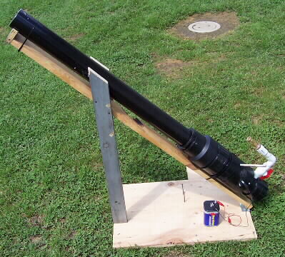
Above are pictures of the fullly assembled launcher from two
angles. The wooden base that it is strapped to was constructed
from scrap lumber and a hinge to set the 45 degree launch angle.
|
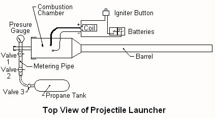
This drawing dipicts a top view of my revised first effort. It had been
upgraded to a coil ignition from the bar-b-q igniter that died, but had
no rear vent or mixing fan. It would usually fire the first time, but then
be difficult to fire thereafter due to lack fresh air and fuel mixing problems.
The pressure gauge also did not retain it's high reading, so it was hard
to be confident of the pressure obtained during combustion.
|
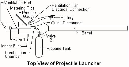
This depicts the top view of the current launcher. Note the tire pressure
gauge that retains its high reading unitl reset. Works very consistently.
|
The top drawing depicts the itemized parts needed. The lower drawing
shows the basic dimensions of the launcher.
|
|